Documentation
JAL-modules and
test-program
for a radio-link
using
RF12B modules
tested for PIC 16f876 and 16f73
Autor: H.v.Broekhuyzen
Content:
1) Scoop 3
2) Background. 3
3) Requirements for the test-programs. 4
3.1) Both PICs must be able to send and receive. 4
3.2) There must be an echo test to check correctness of the link. 4
3.3) The receiver must also be able to detect a corrupted package. 4
3.4) There must be a variation on the echo test where the test-slave echo's signal 0 if the received payload is OK and not responds (or with another reserved signal) if not. 5
3.5) The time times must be measured and printed. 5
3.6) The length of the payload to send must be adjustable. 5
3.7) The results of the echo-test and its behavior must be shown on LEDs 5
3.8) The delay-time before the echo-master restarts a new test must be adjustable. 5
3.9) There must be an adjustable delay-time between receiving a package and echoing it back to the echo-master. 5
3.10) It must be possible to switch off printing by echo-master and echo-slave. 5
3.11) It must be possible to change the RF12b's settings of : Center-frequency, Bandwidth and Data-rate in any combination. 6
3.12) It must be possible to study the influence of other transmitters in the same frequency band. 6
3.13) It would be nice that all 3 modules report to (and be controlled via) only one PC. 6
3.14) The echo-test must be started automatically after power-up. 6
4) The hardware. 7
4.1) Construction. 8
5) The software. 10
5.1) Involved files and their purpose. 10
5.2) Difference of the software for the 3 PICs. 10
5.2) Structure of Commands 10
5.3) Available Commands , their purpose and actions. 11
5.3.1) General use of the LEDs. 11
5.3.2) Table of commands 12
5) Getting started. 14
6) First experiments 14
7) What if there is trouble to shoot. 15
8) Suggestions for experiments 15
8.1) Range check. 15
8.2) Observe timeout 15
8.3) Influence reported times 15
8.4) Find limits for combination of bandwidth and data-rate. 15
8.5) Run test like the suppliers demo-program. 16
8.5) Use frequency setting to avoid interference by jammers. 16
9) End notes 16
This document accompanies some files that are proposed to be included in JALLIB, an open-source library for programming PIC micro-controllers. See: http://groups.google.com/group/jallib and http://code.google.com/p/jallib/wiki/JalapiWelcome
In combination with files in Jallib the proposed files are everything there is needed to compile
programs to experiment with RF12b transceiver-modules, and test their performance under different conditions and different settings for the modules.
This document also describes the hardware needed to run these programs.
Further, it includes a condense User Manual for the test modules and suggestions for experiments.
Up to the beginning of this project I used a bluetooth dongle for wireless communication between my PC and PICs, and for communication between PICs, I used infrared links
like the one used for TV remote-control.
The first one is easy to use but rather expensive. The second one is cheap, but has its drawbacks. When I found the RF12b (430 MHz band) modules in the web-shop of the founder of JAL for 1/7 of the price I paid for the bluetooth dongle I became interested.
After a quick scan of the manual, and the conclusion: “Not simple but with promis”, I ordered a couple and stuff they need.
When I studying the manual and the demo-program I concluded: “This is incomplete”.
Google brought me to http://blog.strobotics.com.au/tutorials/rfm12-stuff/ who explained more. It also brought me to https://loee.jottit.com/rfm12b_and_avr_-_quick_start
where a demo-program in C for an AVR is published and is stated that the demo-program is not completely correct.
Both demo-programs aim only for having one controller send something and the other
receiving and sending it via RS232 to a PC with terminal emulator. A lot of functions of the RF12b module are not addressed.
So I decided to make software (in JAL) to try-out more and to design library files for future applications.
After studying the documentation and websites mentioned above, it was clear to me that it was out of my reach to use 2 RF12b's for a full-duplex link. So I settled for half-duplex communication, that is data-traffic is one way at any time.
Another thing that became clear is: Bytes must be sent in 'groups'. Pauses between bytes are not allowed because there is no method to detect the beginning of a sent byte, but there is a
facility to detect the beginning of a group of bytes. This facility uses transmission time (at least the time to send 4 bytes) so sending each byte in a separate 'group' will slow down the data-link.
There is no support to detect the end of such 'group' of bytes. When transmission stops, the receiver must 'know' in some way that the end of a 'group' of bytes is reached.
To solve this, there are 3 options:
The
groups are of a fixed length which is known by sender- and
receiver-PIC
This is only effective in special situations.
One
special byte (like a zero) is appended to the end of the group to
indicate the end.
This is easy to implement, in the C language
ASCII-strings are zero terminated. But for non-ASCII bytes, a zero
may be in the middle of the group.
One
extra byte is added to state the number of remaining bytes in the
group.
In the remainder of this document we call an extended
group a “package”
and the original group of bytes: “payload”.
As last I learned from reading websites that the longer packages are, the more chance there is
on damage by interference caused by other RF-sources. That is why I settled for a maximum payload-length of 127.
Next elements to study, and so the requirements for the test-program, where inspired by
observing my grandsons while they communicate via a set of walky-talky's and the things are going wrong there.
I was not aware of all requirements at the beginning of the project, but I knew that more requirements would surface. So I designed the software extendable.
The simple tests as in the demo-programs must be possible in both directions.
For this test, one PIC serves as Test-master, and the other as Test-slave. The test-master transmits a package. The slave prints length and payload, increases the value of every payload byte with 1, and sends the changed payload back to the master. The master checks every byte
and reports. Than after a adjustable delay it repeats the test with a new payload.
This continues until the test is stopped via command typed via PC and RS232.
For this the transmitting node adds one byte to the package after the payload. This byte is called CRC-byte. The value of the CRC-byte is calculated from the other bytes in the package, that is: length of payload and payload bytes. The receiving node can use the same calculation and check if the extra byte received is OK.
Note1: The transmitter can send packages in which the payload-length is defined as zero, or even a negative value. We call this packages a signal. In case a signal is transmitted, no CRC
is added in the package so the package consists only of the length-byte. The meaning of signal -4 … 0 is predefined (see description in sources)
Signal 0 is used as ACK (acknowledge) signal. A term used commonly in communication software. If no ACK signal does not arrive within a given time, the package can be retransmitted. Other reserved signals serve as NACK signals.
This is: the time to to send a packet, time spend to wait on- and to receive the echo, and the to
total turn-around time.
This is to study the influence on times and reliability of the link.
The applicable range of the data-link must be tested, so one has to be able to move the circuit serving as echo-master while it is not connected to RS232, and see on what distance, and environment conditions, errors appear. In this case the circuit is batery powered.
At short delay-time will result in data fast scrolling over the screen of the terminal-emulator and so, the text will be not readable. On the other hand, executing a lot of test in a short time speeds up the judgment of reliability.
This is to prevent that the echo-master missis an echo because it has to switch from transmitting to receiving. (as I observed by my grandsons).
Only in this way, the highest frequency of tests can be reached.
The demo-programs from the supplier and the one I found on the internet, do not stress the
RF12bs to their maximum performance. They only want to show: “Look it works!”.
With the functions for this requirement it has to be possible to investigate the real limits at given distance and environment conditions.
In theory the Center-frequency of the RF12b can be set to 4096 different values in teps of 2,5kHz, and the bandwidth can be adjuster to 6 values (67 kHz ...400 kHz).
The answer to find is: What are the requirement when more that one pair RF12b operate in the same frequency-band, and how resistent is the link for other HF-sources.
Note: For this I ordered a third RF12b so a third module can act as jammer.
So for this, 3 PICs and 3 RF12b must operate, report, and being controlled.
In this way the sequence of events appear on one screen. The method for this and corresponding software, was copied from an earlier project.
When we are testing the reliable range of the link, the module serving as echo-master is battery-powered and mobile. Auto-start of the test prevents that we have to connect the PC to start the test.
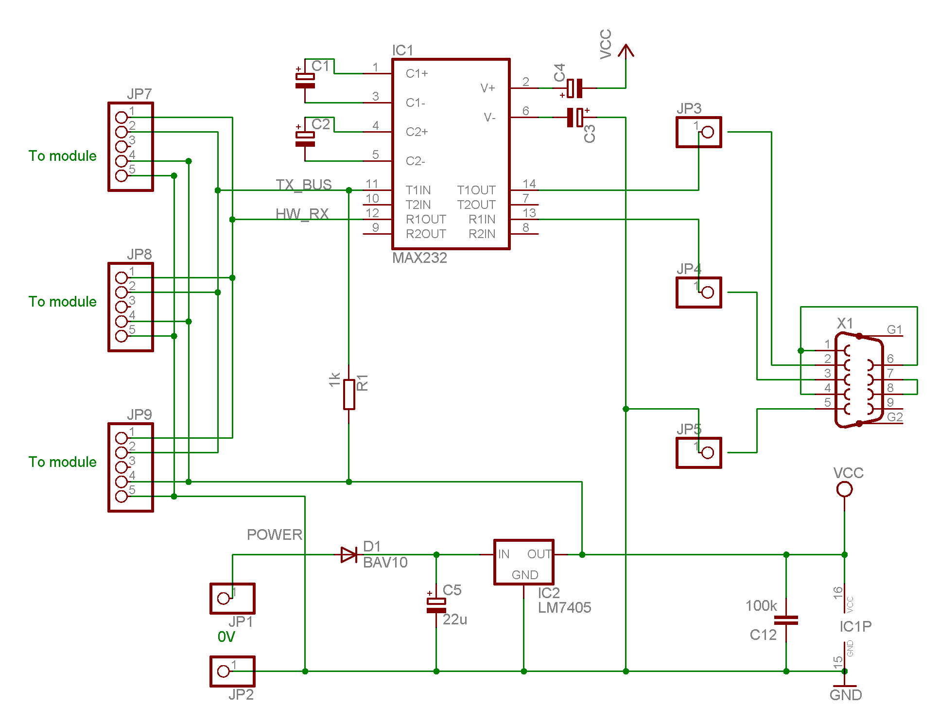
The hardware for the tests was build in 4 modules, 3 the same modules with a PIC and a RF12b and one module to connect the PICs to a serial port of the PC.
Next figure is the schematic the RS232 circuit which differs only from the commonly know circuit by the presence of the resistor R1.
The circuit of the 3 modules with PIC and RF12b is:
M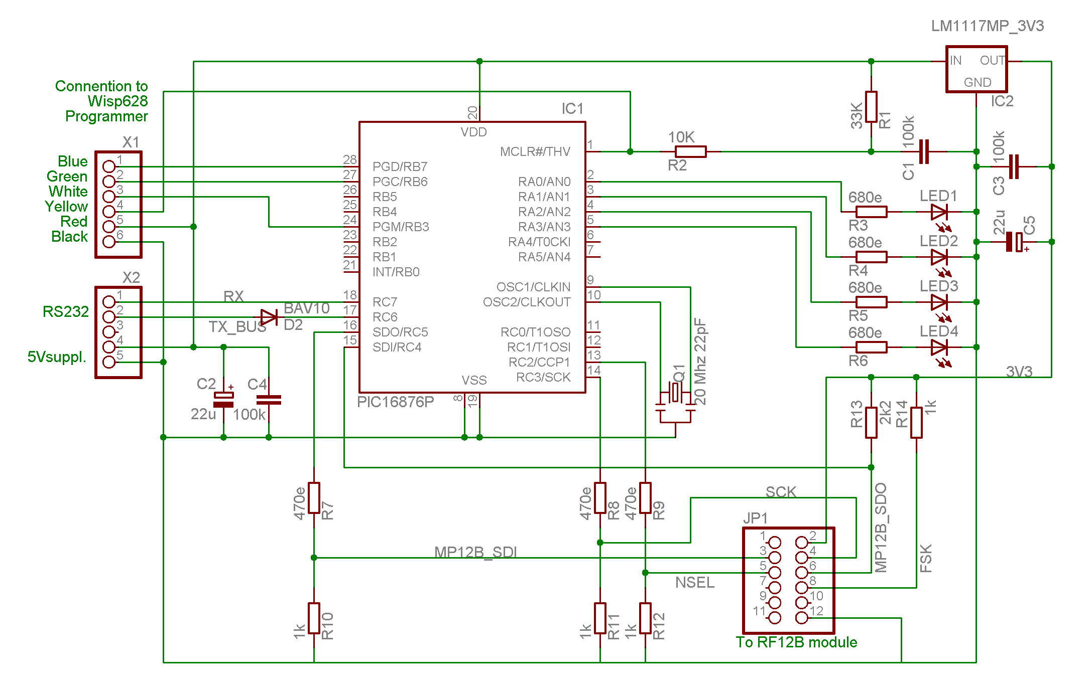
ark
that there is a diode D2 is the TX line of the PIC. Together with
the R1 in the first diagram they form a gate that takes care of
requirement 3.9. All 3 PIC's can send characters to the PC, only not
at the same time (if they should, the PC would receive garbage, but
the PIC are not damaged because of pulling the same line up and down.
All RX inputs of the PIC's are connected together, so what is typed on the PC and its terminal-emulator arrives at all PICs. This subject is address further in the chapter “Software” below.
The RF12b are to be supplied with max 3.9 V so there is a 3.3 voltage
regulator IC2 at the right top of this diagram. I decided to run the
PIC's on 5V for easy use of my Programmer.
The connection to te
programmer is shown top – left. The connection to the first
circuit diagram is shown below the connector to the programmer.
R7 .. R12 adapt the output levels of the PIC to the input levels of the RF12b. R13 is a pull-up resistor, because the used input port of the PIC does not have one. R14 is mandatory for the way we use the RF12b. All other is evident.
The PIC's shown in the diagram are 16F876's, for 2 of my modules I used pin-compatibel 16F73 I had laying around. The only change is the software is including the correct library.
I build the 3 test-modules on 3 small solderless breadboards as on pictures below.
Two problems had to be solved:
The Rf12b module has 12 pins (2 rows of 6) on a pitch of 2 mm and the 3.3V voltage regulator is of SMD format while the breadboard has a pitch of 2,54 mm.
I designed two solutions. I do not describe the first one that involves pieces of experiment print and header pins, because I think the second solution is dominant.
For the RF12b modules I bought a fitting connectors advertised on the website near the RF12B modules. I bend the pins outwards, and soldered the end of the pins on top of a high-quality 14-pin DIP IC socket (the kind with round buses). The two remaining pins of the socked where connected to the small pins of the voltage regulator and its output is connected to the Vcc pin for the RF12b as in next picture:
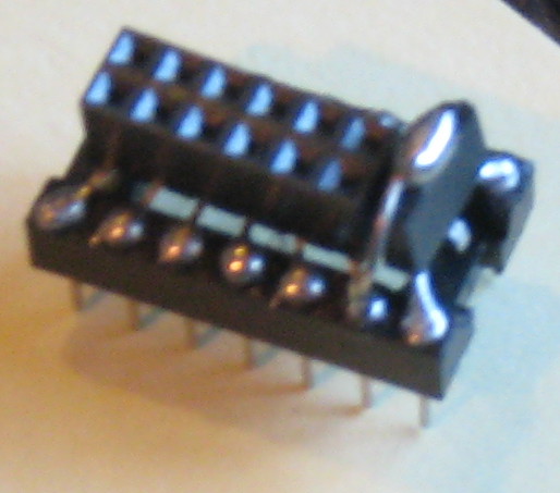
Do not confuse the pin-numbers of connector in the circuit diagram and the pin-numbers of the IC-socket.
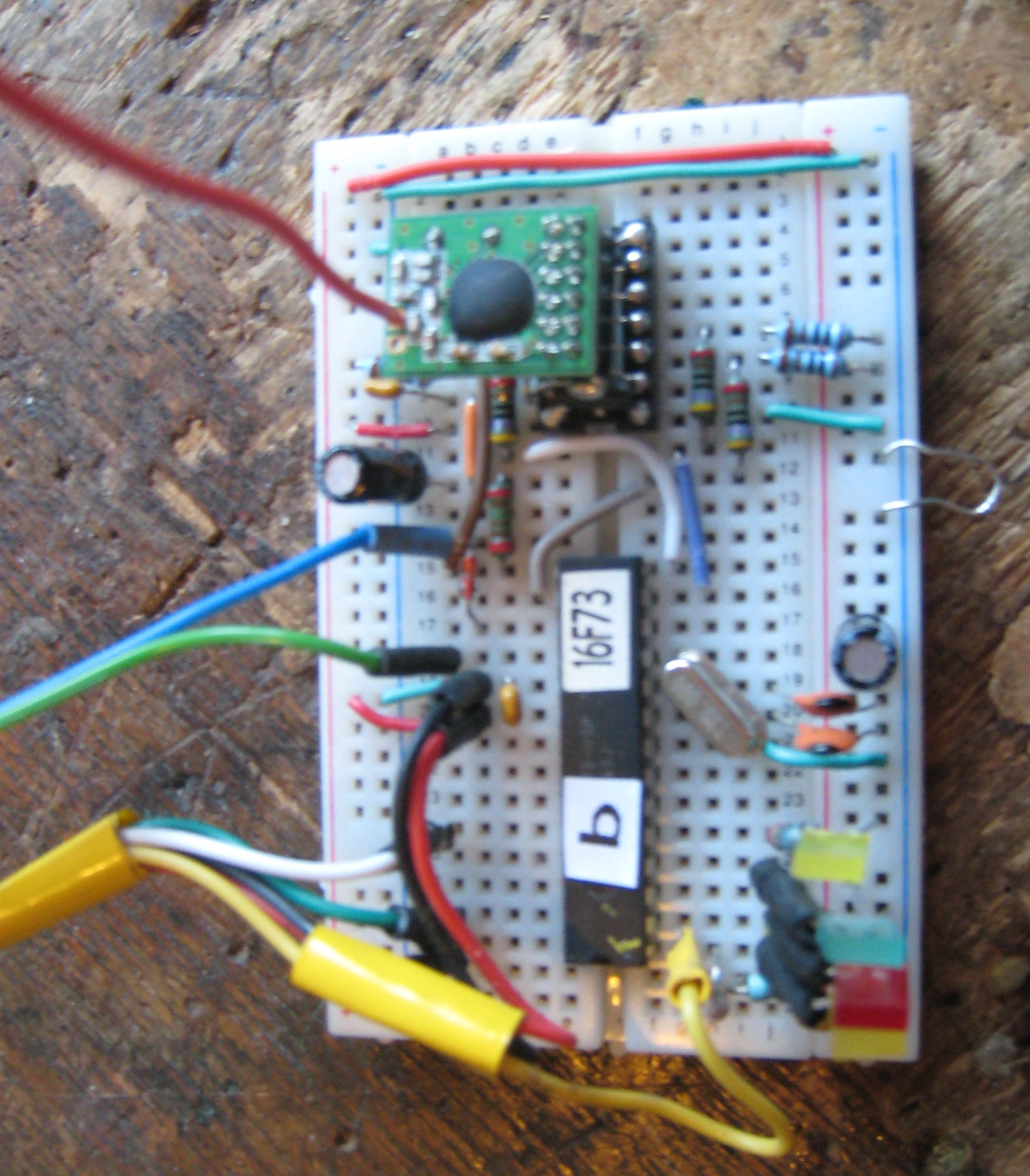

breadboard with RF12b module Without RF12b module
Beside of the files already in JALLIB, the programs for the RF12b test is compiled with the following files:
tstRF12Main.jal,
tstRF12com.jal
tstRF12sub.jal
T0comInISR.jal
spi_RF12B.jal
spi_sw_master.jal
The files: tstRF12Main.jal, tstRF12com.jal, tstRF12sub.jal and T0comInISR.jal form the demo-software for the other files and realize all requirements listed above.
TstRF12main.jal includes all what is necessary and defines and initializes global data and constants.
Tst_RF12com.jal interprets command you type to the PIC via RS232 and executes corresponding actions.
Tst_RF12sub.jal contains test procedures and functions called in tst_RF12com.jal.
The files: spi_sw_master.jal, spi_sw_master.jal and T0comInISR.jal can be used unchanged in other projects. The procedures and functions in these files are documented the the header of these files.
The program for the 3 PICs are are compiled from the same files. Only one constant definition at the beginning of tstRF12Main.jal (CFG_ControllerID at line 37) has to be set to an unique value for each PIC. Let is use the values “a” , “b” and “c”.
As the hardware around all PICs is equal and the software is equal but for the this one constant, they all can perform the same actions, e.g. they can act as echo-master, echo-slave and jammer.
What role the have to perform (and a lot of other things) it made clear to them by typing commands on the connected PC with terminal-emulator.
Remenber from chapter “The Hardware” that what is typed on the PC arrives in all PICs.
A command consists of 4 parts: “who”, “what”, “how much” and the character typed with the enter key.
The “who” part should be equal to one of the defined controllerIDs (in our case: a b or c).
The “what” part is a non-numeric character that specifies an action to excecute. We call this character command character.
The “how much” part is a numeric value in the range -320768 … 32767 (sword) that is past to the software part that execute what is ordered via the “what” part.
The enter-key is typed when you are sure that all what is typed is OK.
Mark that:
you can not use the backspace to correct typing errors, but you can hit the “esc” key to begin all over again
characters do not appear in the PC screen when you type (no local echo by the terminal emulator), but the PIC that is addressed will print it on the screen when the command has been completed (not in special cases)
if the “how much” part is blank (no characters typed for this) a zero is assumed.
You can type commands to a PIC while it is still executing a command. Only a limited set of the commands (with very short execution time) are executed during the run-time of a previous command. We call these commands parameter commands.
When the PIC has a action programmed for a received command character it indicates the start of execution by printing its Controller_ID. If it has not, it prints a “?”.
There is one exception on this: If the H key is typed as “who” part, all PICs get the Halt commands immediately. So it is short for ah<enter>, bh<enter> and ch<enter>.
For more: Read the heading is file T0comInISR.jal because this contains the interrupt routine that monitors the RX input of the PIC. I filters out the commands aimed on its PIC, and passes the command character and corresponding “how much” value to the main program. It also sets a flag-variable when it has passed a command. The main program test this flag for the arrival of a command when it is ready to execute it and reset the flag when it starts execution.
Actions ordered by a command that can loop for long times, can check if the “new-command-flag” is set, and if so: terminate the loop.
It can also check if the 'new command' is a command with a very short execution time (a parameter-command) and if so insert the action of that command in its loop. In this case
noting is printed.
As this document is written as introduction to available source-files, this chapter is kept as short as reference sheets.
Mark that the first character of a command (the controllerID) is left out. You shout by now understand why.
LED1 (Yellow) is on when the execution of a command is in progress.
LED2 (Red) flashes on when an echo-test fails.
LED3 (Green) flashes when an echo-test was OK.
LED4 (Yellow) is on while the RF12b is waiting on- or receiving input.
See next page.
|
Com-mand |
Action |
Param-Com. |
|---|---|---|
|
"b" |
bandwidth in RF12b's Receiver Control Command (init sets 4). 1= 400, 2=340, 3=270,4=200, 5=134, 6=67 kHz |
-- |
|
"c" |
RF12B clock output in state <ComValIn> & 0x0007 A command only useful when testing communication PIC → RF12b. |
Yes |
|
"d" |
data-rate Command (init set 71 =~ 4800 bps, smaller is faster) |
Yes |
|
"e" |
Master echo-test (until next (non-parameter) command). Send a packet and receive a packet. Command E on other node It should have raised al bytes in the packet by 1 Flash LED2 in case of error or trouble, and LED3 if OK This command executes parameter-commands. |
-- |
|
"E" |
Echo-slave = Receive a packet, raise all bytes by 1 and send it back, print it,Repeat this until next (non-parameter) command. This command executes parameter-commands. |
-- |
|
"F" |
FIFO clear. (Was only useful during development) |
-- |
|
“f” |
Frequency Setting Command ( (init =1600) +/- 2.5 kHz / unit) |
Yes |
|
“H” |
Halt command (without printing or confirm) |
|
|
“h” |
Halt. |
|
|
“i” |
Initialize RF12B as automatically after power-up |
-- |
|
"l" |
Length of packet send by command “e” (or signal, see spi_RF12.jal) |
Yes |
|
“m” |
RF12b Mode: 0 = OFF , > 0 = transmit, < 0 = Receive |
-- |
|
“p” |
Set PrintInEchotestMask. See description in tstRF12main.jal. General: 0 = nothing, 255 = all) |
Yes |
|
“r” |
Report byte in FIFO (Was only useful during development) |
-- |
|
“R” |
switch to Receive mode and report received bytes until 0 ; (until new (non-parameter) command). Slave for command "T" This command executes parameter-commands. |
-- |
|
“s” |
report Status log (last one is now) |
Yes |
|
“t” |
timeout (in ms) for response (used in command e) |
Yes |
|
“T” |
Transmit until new command a zero terminated ASCII-string (developed before command e and E) Teams up with Command “R”. This command executes parameter-commands. |
-- |
|
“W” |
wait-time (in ms) for command E (delay in send-back) |
Yes |
|
“w” |
wait-time for command e and T (delay in loop) |
Yes |
|
|
|
|
Tabel 1: Table of commands in test program of RF12b
After you build the hardware: setup your terminal-emulator to 115k2 baut, 8 bits, no party, no
echo.
Connect (temporarily) the 5V- RX and TX lines and check that characters you is typed appear once on the screen.
Unplug the RF12b module from the test-module “a”, power it up and compile and load the program. When the program starts, all 4 LED's should blink a couple of times, and then
LED1 is on continuously, and LED2 and LED4 blink. This shows that command “e” was activated during initialization.
Make shure the RX and TX lines are connected and type: ah<enter>. All LEDs should go off.
Congratulations: You have successfully given your first command. Now type as<enter>
The PIC will show the status log.. All bits on the last line should be 1 (because the RF2 module is unplugged). Power-off, connect the RF12b module, and power-up again.
See that the LED behavior is like before. Type commands ah<enter> an as<enter>. again.
The last line of the printed status log should now report all zero's.
Type command ae<enter> and see that blink as before.
After changing the constant CFG_ControllerID (at line 37 of tstRF12main” from “a” to “b”, repeat the process for test-module b.
The LED behavior is different to that of module a, because command “E” was activated during initialization. LED1 and LED4 are on continuesly.
Use commands bh<enter> and bs<enter> and see equal reaction as with module a.
If you build also a module c (what is optional), what you did for a and c, After blinking all LEDs go to off because no command is activated during initialization.
Power of an make sure that both RF12b modules are plugged in.
Power-up, and Bingo, the echo test should be running. On both modules LED1 is on, and LED3 and LED4 flash. What is going on is reported on the PC's screen.
To understand this all you have to study the source.
While this test is running type aw2000<enter> and see that the test is repeated at lower rate.
Type aw<enter> and see this rate going up.
Type aw1000<enter> to go back to initialised rate.
Type bp<enter> and see that command E in module b does not print anymore.
Type bp255<enter> and see that command E resumes printing.
Type al5<enter> and see that the packet length is changed to 5 characters.
All commands above are parameter-commands, that is they can also be used while a test is running.
Now type H and see that both modules Halt.
For fun: type be<enter> and aE<enter> and see that the modules switched roles.
Type H again, and type bR<enter> and aT<enter> and observe a more primitive communication test like the manufacturer's demo-programs.
Now you are introduced, so you can be inventive to execute tests you dream-up, by series of commands.
As this is no beginners application it is assumed that it is assumed that troubleshooting PIC and communication with the PC is no subject for this document, but working with the RF12B is.
1 ) If after initial flashing LED2 and LED3 stays on, there is a hangup in SPI_RF12B_Init(), most likely because the PIC's input SDI is not pulled high by R13.
2) If the echo-test does not run, the communication with one of the RF12B modules might not work. To test this, you can use command “c” that uses the SPI bus to control the frequency of the clock output of the RF12B modules. This is a very simple function, involving non of the RF12B's HF-circuits. Command “c” keeps setting this frequency in a loop until you give a new command. So you can check the SPI signals with a scoop, or a logic-probe. Even with a normal voltmeter you should be able to detect that the avarage voltage is not as the normal low or high levels.
3) Use command “s” and try to understand the status-log.
Disconnect module “a”, the echo-test-master, from the RS232 and power, and power it with 3 batterys or 4 Ni-Mh-accus. Observe the LEDs and walk around.
In my house the echo-test did not fail in my whole house, despite 2 concrete floors between master and slave. Outside the hause, the specified range of 30 meters ore more appeared to be real, but for one remark. While moving, it the connection failed regularly. When I stopped, the test showed no errors. .
My idea is that this is because the bandwidth is set rather wide (200 kHz) so the module might need much time for auto-lock.
Anyway: Retransmission when not receiving an ACK-signal might be worthwhile.
With all RS232's connected, type bh to stop the echo-slave, and see in the PC's screen that the master times-out receiving after 500 ms. You can change this time using command “at”
Use command “W” to set the delay-time of the echo-slave, and command “w” to change delay before a new test is started.
Use command “d” for both modules to increase the data-rate.
Experiment using command “b” to change bandwidth and “d” for data-rate to find and optimal combination for your application,
Type command R for one module (e.g. aR) and for the other module (e.g bT).
Here too, you can speedup the repetition using command “w” (e.g. bw10).
This test can of-cause only be executed when you build a third module with ID= “c”
While the echo-test is running, start command cT and see that the echo-test fails when
Module c transmits at the same time as one of the other modules.
Now change the frequency of module c (cf...) until the echo-test is not jammed anymore.
Mark that the bandwidth-setting of the echo-slave has also influence.
Try the same but use command cm1 (c to transmit mode) to jam.
If you find more optimal setting for bandwidth and data-rate that set by procedure SPI_RF12B_Init() or if you want more links in the air that use different frequencies, you do not have to addapt procedure SPI_RF12B_Init(). SPI_RF12B.jal includes procedures that can be called after SPI_RF12B_Init() to change settings.
I postponed further test because in the web-shop where I bought the RF12B's appeared RFM70's. These are even cheaper, and , according to their documentation, equipped with more elaborated functionality (and as I expect a lower range). So I give priority to get them up and running for comparison. But that is another project.
Eindhoven, march 2011.
H.v.Broekhuyzen
Printed